Unboxing and assembly of the Razer Core X eGPU
- Articles
- 27 July 2026 at 13:47 UTC
-

- 2/3
4. Razer Core X eGPU enclosure assembly
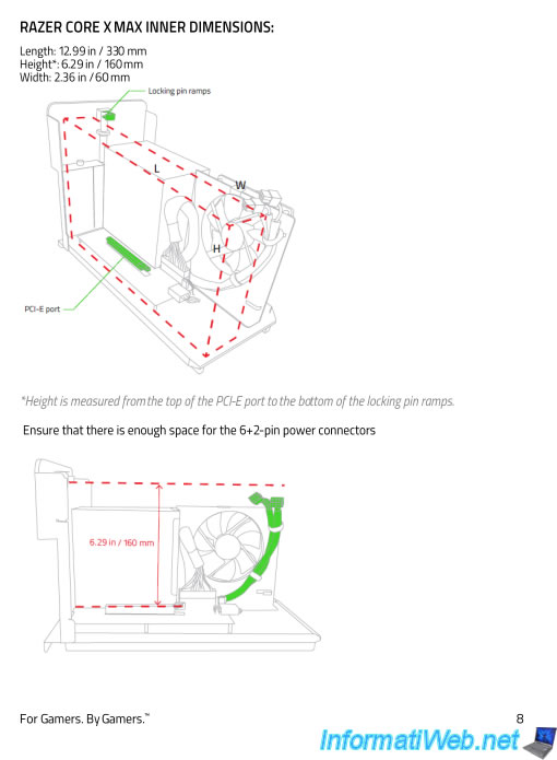
Before mounting your graphics card in this "Razer Core X" eGPU case, make sure that it fits into the case.
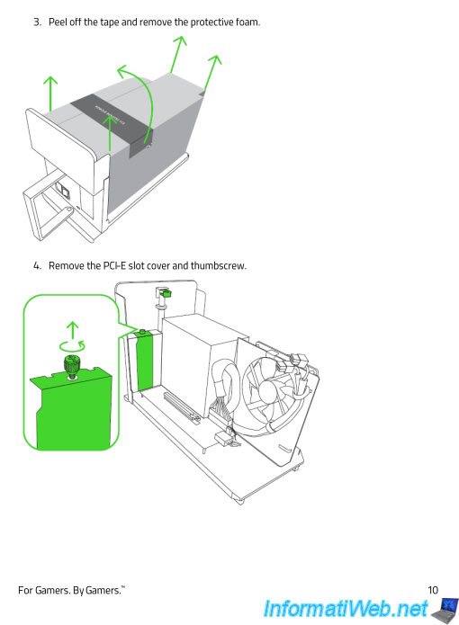
To do this, refer to the manual provided with the case, a copy of the relevant page of which can be found below.
As you can see, you must ensure that your graphics card does not exceed the dimensions indicated on the plan.
In addition, there must be enough space for the power connectors (2 x 6+2 pins).
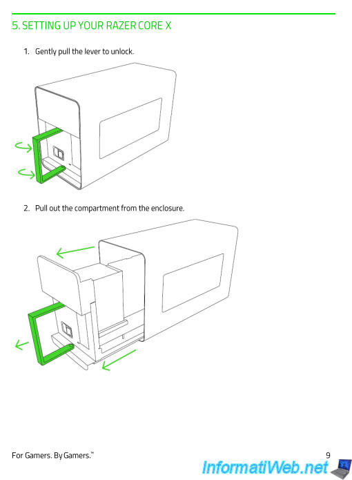
To open the case, you must unfold the handle located at the back of it, then pull it to take out the compartment that is inside the case.
Note: this compartment is not attached to the inside. So you do not risk tearing off a cable or anything else. Don't worry.
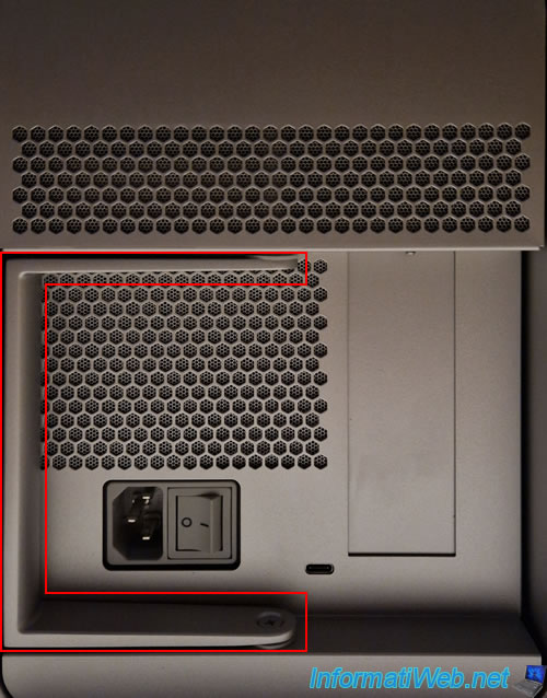
As you can see, by default this handle is folded to the left at the back of the case.
Unfold it so you can shoot it.
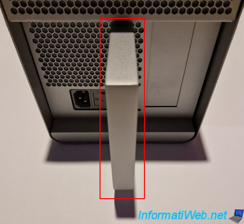
Pull this handle to take out the compartment present in this case.
As you can see, by default, a protective foam that you will have to remove is inside the case.
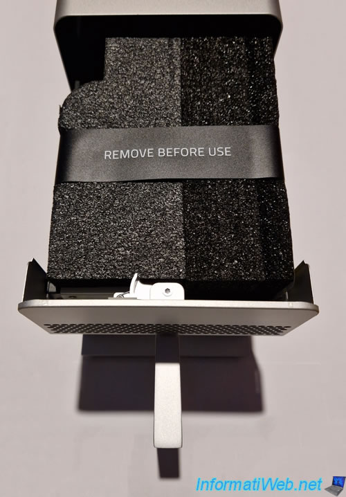
Note that this protective foam will also allow you to check the size of your graphics card.
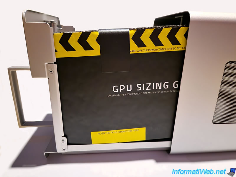
As instructed in Razer's manual, remove this protective foam from the case.
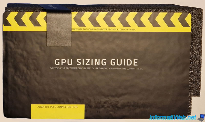
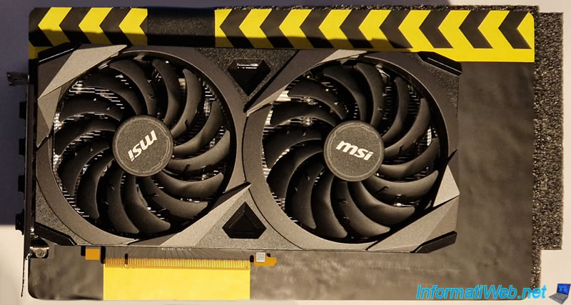
As you can see, the yellow and black paper allows you to verify that your graphics card will fit into this case without any problem.
In our case, we purchased a graphics card "MSI GeForce RTX 3050 VENTUS 2X 8G OC LHR" as previously stated in the prerequisites of this article.
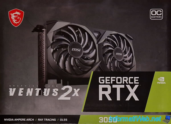
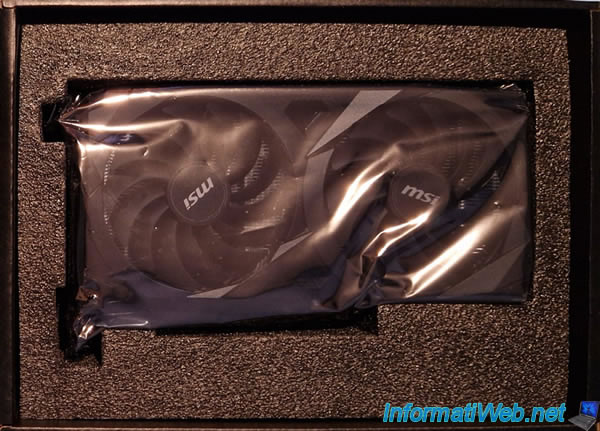
This is what the graphics card looks like in its packaging.
To check the size of your graphics card, align the PCIe connector on your graphics card with the small yellow rectangle at the bottom.
Note: It is therefore normal for the PCIe metal bracket to protrude from the paper on the left.
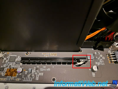
This is what the inside of the "Razer Core X" eGPU looks like.
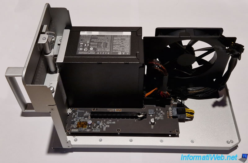
In short, there is a printed circuit board with at least one PCIe slot to plug in your graphics card (not supplied).
Important : remember to unlock this PCIe slot before trying to plug in your graphics card, otherwise it will not fit.
However, pushing it into the connector will automatically lock this little clip.
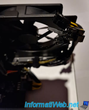
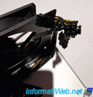
On the right, you will find 2 cables with 2 connectors each (6+2 pins).
Note: in total, there are 16 pins.
Next you need to unscrew the screw that holds the metal cover for that PCIe slot.
Unscrew the screw to remove the metal cover.
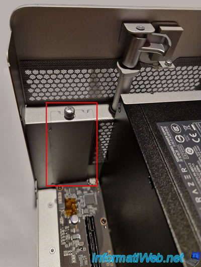
Once the screw is unscrewed, you will get this back.
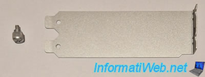
Now, the metal cover is removed.
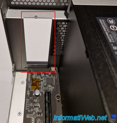
Share this tutorial
To see also
-
Articles 11/30/2016
Digitus - HDD case with hardware encryption
-
Articles 1/16/2023
Hirschmann INCA 1G - Pass the Ethernet network through the Coaxial cabling
-

Articles 7/11/2014
How to partition a hard drive ?
-
Articles 9/16/2024
Intel NUC Skull Canyon - Install Windows 10
No comment